CPR E 381x/382x - Lab 8b
Tractor
Meter
1. Objectives
In the first sections of
this lab, we learn more about the basic digital input/output devices (switches
and LEDs) on the PowerBox. We will often
use this I/O in the lab to represent user or environment input, such as from
buttons, dials, etc. Memory-mapped I/O is also defined. The rest of the lab
describes an embedded programming exercise in the application domain of
"smart farming." You will need to write a C program.
1.1 Reference
Files for Lab
2. Prelab
Read
all of the lab sections, there is a lot of info, which will take awhile to read
through if you wait until lab time.
Begin to design your software, even if only pseudo-code.
3. Setup
As
you did in previous labs, make sure you create the folder in your home
directory U:\CPRE381\Labw07b to save all your work from this lab.
In this section, you will learn a few more
details about the PowerBox digital I/O components. To begin, here is some
helpful terminology:
- Bus - A collection of wires sharing a common purpose
- Latch - A flip-flop used to keep data (latches on a clock signal)
- Buffer – Stores and transfers data, typically having outputs in
three possible states (low, high, or high impedance (open circuit))
In order to read/write data to the
outside world, the PowerPC processor sends signals on a collection of wires
known as a bus. The three main bus types for any computer
system are:
- Address - Who
is the processor talking to (RAM, ROM, hard disk, temperature sensor,
etc.)?
- Data - What is
being said (110.6 degrees, 0xFA, "Hello")?
- Control - Who
is doing the talking (device, processor)?
Now, the PowerPC processor is not
set up by default to interact with the real world. Thus, we need some
components to help the processor interface with the real world. This
introduction is primarily concerned with the digital input and output
components of the PowerBox.
Memory-Mapped
I/O
The PowerBox uses what is known as
memory-mapped I/O. Essentially, memory-mapped I/O can be summarized as
simply putting all devices and memory out in a large memory space. Thus,
when you are using pointers to read and write to memory locations, you may be
using different devices. For instance, memory address 0x2000 may point to
a serial port, whereas 0x3000 may be in a block of
- 0x20000000 - RAM - 16 MB of memory
- 0x40000000 - Digital Input/Output
You will be writing the code for
accessing the digital input/output. You will use constants defined
in the file defines.h, shown partially below.
// Defines.h : Definition file for PowerBox
////////////////////////////////////////////////////////////////////
// Overall memory addresses for external I/O board
// 32 bit
pointer
//
#define ADDRESS_START_EXT_RAM 0x20000000
#define ADDRESS_START_EXT_IO 0x40000000
/////////////////////////////////////////////////////////////////////
// I/O ports
// All I/O
ports are 8 bit ports
#define IO_DIGITAL_INPUT_1 0x40000003
#define IO_DIGITAL_INPUT_2 0x40000007
#define IO_DIGITAL_INPUT_DIP_1 0x4000000B
#define IO_DIGITAL_INPUT_DIP_2 0x4000000F
#define IO_DIGITAL_INPUT_KEYPAD 0x40000013
#define IO_DIGITAL_OUTPUT_LED1 0x40000023
#define IO_DIGITAL_OUTPUT_LED2 0x40000027
#define IO_DIGITAL_OUTPUT_1 0x4000002B
#define IO_DIGITAL_OUTPUT_2 0x4000002F
#define IO_DIGITAL_OUTPUT_7SEG 0x40000033
#endif
Digital
Input
To read information in from the
external I/O board, the PowerPC processor does a read to a memory address in
the 0x40000000 memory address space. The circuitry for the digital input
circuit looks something like the following:
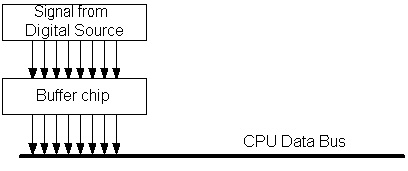
The outside world digital source
may come into the PowerBox via either the DIP switch or the Digital Input
channels as digital signals. The data itself is transmitted to the CPU
via the data bus. However, the CPU uses the data bus for more than just
reading digital input. Thus, a buffer chip is required that places
information on the data bus only when it is requested by the CPU. When
the CPU wishes to read information from one of the digital inputs, it signals
the buffer chip to allow it to change the data bus. The chip changes the
data bus and the CPU reads the data bus to get the value of the digital input.
The buffer chip serves a second purpose
as well. On the data bus, there are several devices waiting to read/write
to the bus. On the PowerBox, there are 10 different input/output
ports. However, what happens if each of the devices tries to talk at
once. Suppose one device drives a data pin with +5V and another device
assigns it 0 V. Who wins? In this case, nobody. The system
ends up having nonsense most of the time and does not work.
The solution is to place the
outputs of devices that are NOT talking on the bus into a high impedance state
(i.e., looks just like an open circuit). Such a device is effectively
disconnected from the bus. By doing so, all of the devices can share the bus
and take turns using it as specified by the CPU.
Digital
Output
The digital output case is fairly
similar with a small twist. Instead of waiting to change the data bus,
the output circuits receive their values from the data bus. Since the
data bus is used for many different purposes, will the data bus contain the
desired output value? The answer is no. Therefore, we need to
include a latch in the circuit as pictured below:
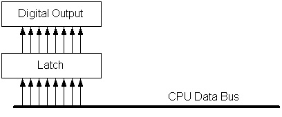
A latch is essentially a
flip-flop (or set of flip-flops). Most latches come in 4- or 8-bit
blocks. The latch is used to store the value and keep writing out the
same value until the CPU changes it. Think about the LED bargraph and the
7-segment displays. Although the program is updating the output once a
second, the latch is what keeps the same value being displayed when the CPU is
doing other things.
DIP Switch
Input
The DIP switches on the PowerBox
are connected in the following manner:
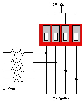
The resistors in the circuit are
known as pull-down resistors. With the pull-down resistors, each
switch value is forced to be either a +5V or a 0V due to the voltage drop
across the resistor.
When the DIP switch is open, there
is not a connection. There is no connection to +5 V and the line stays at
ground (Logic 0). When the DIP switch is closed, current flows from Vcc
(+5 V) to ground and the line rises to +5 V. Notice the connection to ground is
key to forcing the line to appropriate values. The pull-down resistor
prevents a direct connection from Vcc (+5 V) to ground.
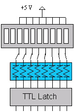
LED Output
In order to power LEDs, there are
two choices, acting as a source for the current or acting as a sink for the
current. However, if you look at TTL logic sheets (see TI's website), you will notice that ratings are
given for both current sourcing as well as current sinking. Typically, the chip
is able to sink significantly more current than it is able to source. One
must take special care when designing a circuit not to violate the maximum
current constraints of the chip, otherwise you will burn out the
chip.
In a current sink setup, the
TTL chip varies between +5 V or 0 V. The LED receives +5 V. The TTL
chip varies its output between +5 V and 0 V to either turn off or light the
LED.
When the TTL chip outputs a +5 V,
the voltage difference between the +5 V (Vcc) and the TTL chip is 0 (5 V - 5 V
= 0). Hence, no current flows and the LED does not light.
If the TTL chip outputs 0 V, the
voltage difference becomes 5 V (5 V - 0 V = 5 V). Hence, current flows
and the LED lights correctly.
For the above scenario, notice that
a resistor is included in the diagram as well. The resistor is known as a
current-limiting resistor and is critical to the correct operation of the
circuit. Without it, current would flow directly from +5 V into the TTL
chip at a level far beyond what the chip can handle. Think of it this
way, if you connect Vcc and ground (don't do it), what happens? Bad
things of course, you have a short circuit. By placing a current-limiting
resistor between Vcc and ground, the current is limited to an appropriate
level. Remember, I (Current) = V (Voltage) / R (Resistance). How
much current flows if you use a 270 Ohm resistor?
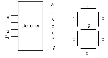
7-Segment
Output
The 7-segment display operates in a
similar fashion to the LED bargraph. However, the 7-segment display
circuit uses a 7-segment decoder to translate from a 4-bit binary value (0000
to 1111) to a 7-segment representation of the respective hex digit (0 to
F). The decoder takes 4 inputs and maps them onto 7 outputs (pins
a-g). For the PowerBox, the 7-segment display includes a built-in
resistor.
Be ready to discuss the digital
input/output ports with your TA as you proceed to use them in the rest of the
lab.
Read the following article on
bitwise operations in C, available online or
from a local
copy. Its explanation is quick and to the point; you should find it helpful
if your background is thin, or easy to skim through for a refresher. You will
need to apply these operations in the program you write for this lab.
Another C coding technique you may
want to review is string formatting, and the following page is a useful
reference: online
or from a local
copy.
You will be using the sprintf
function from the C standard I/O library. Look up the syntax of this function
in the CodeWarrior
C Reference (3.5 MB), under stdio.h.
Don’t forget to use descriptive
variable naming practices in your coding, as discussed in lecture. Follow the
naming conventions used in the example code, or use some variation, but be
consistent. See also prefix
table.
Precision Farming (PF) uses
technology to handle field differences so that farmers can treat fields in a
local way. The goal of PF is, for example, higher profitability, environmental
protection, food safety, and/or higher yields. PF helps the farmer understand
and control the (local) processes in the field. The farmer uses collected
information (yield maps, soil maps, multi-spectral satellite images, etc.), management
decisions, and outputs (fertilizing, drainage, spraying, etc.) for different
goals.
One example of technology
application in PF is illustrated in vehicle networking
for tractors. Interestingly, there is also work going on to develop
autonomous vehicles for farming.
Browse the resource links on the
tractor page, or try a search at google.com (or your favorite search engine)
using “ISO 11783,” “precision agriculture,” or similar to get a feel for the
systems. Obviously, we are not ag engineers or bioengineers, but electrical and
computer engineers and computer scientists are developing the technology for
embedded systems used in PF.
Write a C program that implements a
tractor meter having the following specifications and behavior. Make a new project in Code Warrior, use the
Cpre282x template with the c code option, not assembly.
The meter has three displays:
- Vehicle odometer display
- Plant counter display
- Plants per unit distance display
The vehicle odometer records
distance traveled. The plant counter uses sensors during harvesting to keep
track of the number of plants. Plants per unit distance is the ratio of number
of plants to linear distance traveled.
By default, the output for these
displays should be written to the LCD screen of the QTerm. Refer this code for implementing output to the QTerm LCD. You will use these statements among others.
#include "defines.h" //
Memory addresses for digital I/O ports
#include "QTerm.h" // Output to QTerm LCD
The vehicle odometer is on top with
left-padded zeros. The plant counter is the next line, also with
left-padded zeros. The plant linear density is the third line without left-padded
zeros. Example:
0000010.00 km
0005000 plants
5.00 plants/m
The vehicle odometer starts at
0000000.00 when you execute your program and increments by 0.01 km. It cannot
be reset, unless you restart your program. The density display is set at a
particular rate based on user input, and is limited to one of several values.
The plant counter display increments simultaneously with the vehicle odometer
based on the density reading, and it can be reset to 0000000 by user input.
The meter uses the following
inputs. Study this code to read the digital inputs from
the DIP switches. You will re-use some of that code. You might find it helpful
to draw a block diagram of the switches and label the corresponding bits with
respective functions.
- Set plant density – bits 6 and 7 of DIP Switch 2
[7,6] = 0,0: density = 2.00 plants per meter (or yard)
[7,6] = 0,1: density = 3.50 plants per meter (or yard)
[7,6] = 1,0: density = 5.00 plants per meter (or yard)
[7,6] = 1,1: density = 6.50 plants per meter (or yard) - Set distance unit – bit 0 of DIP Switch 1: If bit
equals 1, use metric units of distance (kilometers for odometer and meters
for density); if bit equals 0, use English units (miles for odometer and
yards for density). You will need to look on the web or another resource
to determine the appropriate conversion factors between units. (HINT:
You may want to keep the internal value in your program as a certain type
and simply convert for the output).
- Reset plant counter – bit 7 of DIP Switch 1: If
bit equals 1, reset the counter to zero. Other displays are not affected.
- Print to PC – bits 0 and 1 of DIP Switch 2: If
both bits equal 1, send the meter values to the PC HyperTerminal via the
serial cable, in addition to the LCD QTerm. The following two files
must be included in your project for HyperTerm Communications. The functions used are very similar to
the LCD functions (i.e. PC_Init() instead of LCD_Init). The third file can just be opened to
start HyperTerm with the necessary settings.
- Serial_PC.c
(save this and include the file)
- Serial_PC.h
(save this and include the file)
- PowerPC.ht
(just open this, no need to save)
Finally, how is the incrementing of
the odometer controlled? Of course, in an actual tractor, a device is built in
to measure distance traveled. In this lab, we will need to emulate or simulate
the device to "imitate" its behavior; that is, your program will
represent the functioning of one system or process by means of the functioning
of another. Emulation usually is done in hardware; simulation, in software. Select
one of the following options to design your program:
- Simulation: Use a while(1) loop in your main program that continuously increments the distance by 0.01 km,
delaying a short time to represent time taken to travel as well as to let
the user observe the meter readings. For example, use msleep(2000) to delay 2000 milliseconds (2
seconds).
while(1)
{
\\ code to increment distance, process inputs, and update displays
msleep(2000);
} - Emulation: Use a DIP switch as an indicator that 0.01 km has
passed. The user flips the switch at any time to represent this distance
has been traveled.
For example, use bit 0 of DIP
Switch 1. Your programming logic may use either of the techniques
below. Note that your software logic may be similar to a finite-state machine
sequence detector, reading a one-bit input, and incrementing in a particular
state. If-else and If
statements can be used to code the logic. (Hint: technique (a) logic can be
drawn as 3-state
(a) Increment distance if user sets the switch: If bit equals 1, add 0.01 km to
the distance traveled.
e.g.,
If bit equals successively 0-1-0-0-1-1-1, program should add 0.01
km 2 times (i.e., each time the bit is set to 1 from 0).
OR
(b) Increment distance if user toggles the switch: If the bit value changes
(i.e., 0 to 1, or 1 to 0), add 0.01 km to the distance traveled. Include
comments in your program describing how your program handles the first value
(i.e., when your program starts up).
e.g.,
If bit equals successively 0-1-0-0-1-1-1, program should add 0.01
km 3 times (i.e., each time the bit changes value).
NOTE: You may experience a phenomenon known as switch bouncing (i.e., one
toggle of the DIP switch results in multiple alternating values of the bit,
e.g., 0-1-0-1). If you are having problems with this, simply add the
following line to your code in the main loop between readings of the switch:
msleep(250);
We will address debouncing in the next lab.
Also, you should give some thought to how you will test your program. For example, you may want to have a version
of the code that implements only one of the tasks in the program. Get that working, and then incrementally add
other tasks. Or you may have a version that implements the control logic only,
and once you have verified the control flow of your program, you start adding
the data processing or input/output statements. Or you might find a particular
piece of the code to be difficult to write, and you could isolate that code and
work on it separately. You have a number
of alternatives to develop and test your program to make your job easier -- so
that you simply do not try compiling everything at once and end up with a long
list of syntax errors.