CPR E 381x/382x - Lab 9b
Tractor
Sprayer
1. Objectives
This lab focuses on program design for embedded applications that control multiple, time-triggered tasks. Viewing a program with respect to its tasks and running those tasks based on time is a key step in designing real embedded applications. This lab introduces simple software architecture to support time-triggered programs. Later in lecture, you will learn more about the timers on the microcontroller.
1.1 Reference Files for Lab
2. Prelab
Read
all of the lab sections, there is a lot of info, which will take awhile to read
through if you wait until lab time.
Begin to design your software, even if only pseudo-code.
3. Setup
Create the folder in your home directory U:\CPRE381\Lab9b to save
all your work from this lab.
In this lab, you will be writing the control program for part of the sprayer system on a tractor. The system to be controlled is two sprayer booms with 8 nozzles each. The nozzles will be represented as single elements of the LED bargraphs.
Nozzles
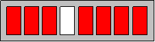
Suppose there are two arms, each of which contains 8 nozzles, as shown below. Each of these arms has two sections, which gives you a total of 4 areas of coverage control (2 on the left, 2 on the right).

The nozzles are emulated on the PowerBox using an array of LEDs, with each LED corresponding to a nozzle. If the LED is on (red in the figure below), then the nozzle is on, or firing/spraying. If the LED is off (white in the figure), then the nozzle is turned off. The figure depicts the light pattern for the nozzle configuration above.
LED Bargraph 1 will be used for the nozzle arrays on the right side of the tractor, while LED Bargraph 2 will be used for the nozzle arrays on the left side. Each arm has 2 coverage areas, an inner and an outer. Use bits 4-7 of the bargraph LED for the inner coverage area, while bits 0-3 are for the outer coverage area.
The sprayer system has a master on/off switch that allows the entire system to be shut off with one switch. Each of the 2 arms has four pre-defined spray patterns when the system is on: test, inner, outer, and all. Each mode corresponds to a programmed sequence of lit LEDs. A set of switches controls which of the four patterns an arm uses.
The sprayer control subsystem uses five binary input switches of a DIP switch to implement the mode controls.
· Set system mode - bit 0 of DIP Switch 1: bit 0 -- 1, turn on the system
·
System
off (bit 0 of DIP Switch 1 = 0): all nozzle LEDs off
· LED Bargraph 1 & 2 - all LEDs are off
·
System
on (bit 0 of DIP Switch 1 = 1): nozzle LEDs follow programmed sequence for nozzle
mode
·
LED Bargraph 1 follows the mode
determined by DIP Switch 1 Bits 2:1 (bits 2 and 1)
LED Bargraph 2 follows the mode determined by DIP Switch 1 Bits 4:3
(bits 4 and 3)
· The patterns and timing are listed below. Be sure to follow the timing exactly.
|
DIP Switch 1 Bits |
Binary Value |
Nozzle Mode |
Description |
|
2,1 or 4,3 |
11 |
All |
Turn on all nozzles for a particular arm, both inner and outer, in a timed pattern. In the array of LEDs, light all even LEDs (bits 0, 2, 4, 6) at once, for 0.5 sec. Then light all odd LEDs (bits 1, 3, 5, 7) at once, for 0.5 sec. Then light all LEDs for 0.5 sec. Finally, turn off all LEDs, and wait 1 sec before repeating the process again. Let * indicate LED on, and - LED off. Sequence of LED patterns: |
|
2,1 or 4,3 |
10 |
Inner |
Turn on inner boom nozzles only in a timed pattern. Light the left-half LEDs, adding one at a time, from right to left, starting at bit 4 and moving outward to bit 7. Each pattern should hold for 0.5 sec. Sequence of LED patterns: |
|
2,1 or 4,3 |
01 |
Outer |
Turn on outer boom nozzles only in a timed pattern. Light the right-half LEDs, adding one at a time, from left to right, starting at bit 3 and moving outward to bit 0. Each pattern should hold for 0.5 sec. Sequence of LED patterns: |
|
2,1 or 4,3 |
00 |
Test |
Turn on each nozzle for a particular arm, one after another, in a pendulum pattern. Light one LED at a time, and shift the lit LED to the left and right, back and forth, at 1/4-sec intervals. The light moves left first, then bounces back to the right, and so on. Sequence of LED patterns: |
For example, to turn the system on (bit 0), set the right arm
(bits 2:1) for the "Outer Pattern" (01), and set the left arm (bits
4:3) for the "Test Pattern" (00), you would set DIP Switch 1 to
0b00000011 (0b is just like 0x in C, it is just a prefix which means a binary
number follows).
Summary of I/O
Inputs
765 43 21 0
bit numbers
DIP Switch 1 Bits: XXX XX XX X
||| || ||
|
Not Used ----------+++ || || |
Left Arm (LEDBargraph2)++ || |
Right Arm (LEDBargraph1)--++ |
System On/Off ---------------+
Outputs
·
LED Bargraph 1 - Nozzles for the Right Arm
(Inner coverage area is bits 7-4, Outer is bits 3-0)
·
LED
Bargraph 2 - Nozzles for the Left Arm (Inner coverage area is bits 7-4, Outer is
bits 3-0)
Program Design
You will follow a top-down design approach and use code templates to create the program for this lab.
Start with the software for your main program. For simple embedded systems, the main program is a so-called “Super Loop,” or endless loop, that will start running when the microcontroller is powered up and will keep running forever (until power is turned off). A Super Loop is used if there is no operating system to run tasks. It is simple, easy to build, debug, test, and maintain. It’s also very efficient, i.e., there is little overhead, for example, in system calls. In practice, many embedded applications will require the features of an operating system to schedule tasks accurately and flexibly. However, let’s look further at the Super Loop code template (also called a software pattern or architecture) in this lab. Refer to the central heating controller example. This illustrates a simple pattern consisting of an initialization function and several tasks (functions) for operating a central-heating system in a building. The simplest version of this system might consist of a boiler, which we want to control; a sensor, measuring room temperature; a temperature dial, to specify the required temperature; and the control system itself. Notice the while(1) loop, i.e., the Super Loop.
Notice also that there is no timing specified. One of the extensions needed for the Super Loop architecture is to perform tasks either periodically or after some delay. A periodic task is performed once every N time units, e.g., once every 100 ms. A one-shot task is performed once after a delay, e.g., after 50 ms. Although we will learn about the use of timers and interrupts later in the course for greater timing precision and control, we can create a simple Time-Triggered Super Loop pattern by adding a delay to the loop, creating a loop that calls functions periodically.
To wait a specified duration of time, use the msleep
function, which takes the number of milliseconds to wait as a parameter.
msleep(250); // Waits 250 ms
Consider the following Time-Triggered Super Loop for the
sprayer control system that repeatedly calls functions every 250 ms. It
determines which mode the system is operating in and calls the corresponding function
for that mode, which updates the LEDs for the nozzles appropriately; it also
calls a status function to update that LED.
// Global variables to hold outputs to LED Bargraphs, set to
all OFF
char pattern_LED1 = 0x00;
char pattern_LED2 = 0x00;
// Super
while(1)
{ if (system is on)
{
//Left Arm Code
if ( Test Pattern is selected, i.e., nozzle mode = Test)
Left_Arm_Test();
else if (Inner is selected)
...
//Right Arm Code
...
msleep(250);
}
else ...
}
Remember: The LED
Bargraph uses a “current sink” to light the LEDs (where a '1' causes the LED to
be off, and a '0' lights the LED). Recall the Output_LEDs function, as
shown in the C coding example.
In this Super Loop
example, the main loop determines the frequency with which each task is
called. It is then the responsibility of
each task to keep track of its own state, the time spent in a state, and take
the required actions in each state based on timing and user input. For example:
void Left_Arm_Test ()
{
static int nState = 0;
// Do something based on nState
nState = nState + ...
}
Notice that this example shows that a task (function) will declare, initialize,
and update its own state variable. So there are effectively separate, small
state machines, one for each task. Alternatively, one big state machine would
declare state as a single global variable, decode the mode, and act
appropriately. With separate state machines, one for each mode, more complex
systems can be managed better. If the modes are called as functions, then state
needs to be remembered from one function call to the next; see the C
"static" qualifer for variables declared local to a function.
The "static" keyword tells the C compiler to create
a space for a variable which exists for the entire run of the program.
Normally, a variable in a function is created when the function is called, and
is destroyed when the function is finished (normally referred to as "auto").
The "static" keyword allows a variable to persist, keeping its old
value for the next time the function is called. The variable is initialized
only once, the first time the function is called. Subsequent calls to the
function skip the initialization.
Consider the C coding example for a task,
which can be used as a template for each of the functions (such as
Left_Arm_Test) in your program. Define the pattern of lights for a particular
function, and modify the switch statement appropriately.
For the Lab
You should create header and source files for the sprayer,
e.g., sprayer.h and sprayer.c, in addition to
the main source file (main.c). main.c should include the Super
Loop, and the sprayer files should define the tasks.
Your super loop may only include one msleep()
call, and should be structured as in the super loop example given above in the
lab. Your sprayer.c file (i.e. the pattern functions) may not
include msleep() calls.
Because of the way your program should be structured, it
should seem like each of the arms is acting independently of the other. If you
change the pattern on one arm, it should not affect the other arm. If you
switch the mode in the middle of a pattern, switching back to that pattern
should pick up where it left off (i.e. the pattern should not start from the
beginning every time you switch to it, it should resume from the point it last
left that pattern).