CPR E 381x/382x - Lab13a
Messaging Service
1.
Objectives
This lab involves writing a relatively large
program using assembly language. As a result, it is expected to pull you up the
learning curve, by putting into practice topics that have been discussed in
lecture as well as by building upon skills used in the lab. This lab also
introduces you to managing a data buffer between I/O devices.
1.1 Reference Files for Lab
2. Prelab
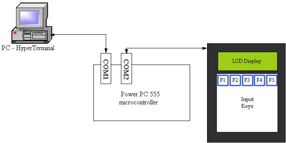
Make sure you have a good understanding of the topics covered in lab 12a. Specifically the use of the COM port to read and write data will be used extensively in this lab. If you have any questions, please do not hesitate to ask you lab instructor.
3. Setup
As you did in previous labs, make sure you create the folder in your home
directory U:\CPRE381\Labw13a to save all your work from this lab.
A. Text Buffer: Buffering Data Between
Input and Output
Write an assembly program that reads a key from the QTerm keypad, puts the key into a data buffer, and writes it to the QTerm LCD display. If bit 7 of DIP Switch 1 is set, send the data to the display – that is, output is active. If bit 7 of DIP Switch 1 is not set, do not send the data to the display – that is, output is suspended. Input remains active. No data should be lost.
·
You
should modify your code from Lab 12a.
Design Components
·
data buffer - QTBufferIn
(for characters from QTerm Keypad)
·
position variables for the buffer
·
input position, i.e., where the next character read in goes
·
output position, i.e., where the next character to be output comes from
·
function Read_QTerm - Reads up to 1 character from COM2 (QTerm) and
places the character into a buffer
·
function Write_QTerm - Writes up to 1 character to the QTerm LCD from a
buffer
Consider the buffer depicted below.
|
location 0 |
|
|
|
|
next input ê |
|
|
|
location N-1 |
|
3 |
A |
8 |
9 |
F |
|
|
|
… |
|
|
é buffer begin |
|
|
é next output |
|
|
|
|
|
é buffer end |
The buffer is of size N characters (bytes). The first character typed on the keypad was ‘3’, placed in location 0 of the buffer. The next character was ‘A’, at location 1, or an offset of 1 past buffer begin. Assume that five characters have been typed in and added to the buffer, and only three characters have been sent to the display so far, i.e., the display reads “3A8”. As a result, the next input location is 5, and the next output location is 3. The buffer could be viewed as an array in C, as follows:
· char buffer [N]
· int position
· buffer[position] denotes an element of the buffer; so for position = 5, gives the element for the next character received from the keypad; for position = 3, gives the element for the next character to send to the display
· buffer itself is the address of the array in memory; so buffer+5 is the address of the next input location; buffer+3 is the address of the next output location
Notice that the next input is always greater than or equal to the next output. If next input = next output, then all characters have been displayed. Your program should work if, for example, output is temporarily suspended, such that new characters received increment next input while next output remains the same.
You should consider and implement a solution to how to deal with the case when next input is past the end of the buffer, as well as a full buffer.
Code Snippets
Several coding examples related to this program are shown below. These are separate fragments.
|
.data ;;;;;;;;;;;;;;;;;;;;;;;;;;;;;;;;;;;;;;;;;;;;;;;;;;;;;;;;;;;;;;;;;;;;;;;;;;;;; ; Memory allocation for data ; QT_In_Pos: .short 0 ; short global variable for input position QT_Out_Pos: .short 0 ; short global variable for output position QTBufferIn: .space 512 ; 512 bytes of storage space for data buffer from QTerm |
|
;;;;;;;;;;;;;;;;;;;;;;;;;;;;;;;;;;;;;;;;;;;;;;;;;;;;;;;;;;;;;;;;;;;;;;;;;;;;;;;;;;;;; ; r21 = key pressed on QTerm ; r22 = address of QTBufferIn array ; r23 = address of QT_In_Pos ; r24 = value of QT_In_Pos ... Add_Key_Buffer: ; Store key pressed (r21) to QTBufferIn + QT_In_Pos stbx r21, r22, r24 ; r21 -> M[r22 + r24] ; Write QT_In_Pos + 1 to move position for added character addi r24, r24, 1 ; increment the QT_In_Pos by 1 sth r24, 0(r23) ; store QT_In_Pos to address in r23 |
|
; r15 = address of QT_Out_Pos ; r16 = value of QT_Out_Pos ; compare the buffer input and output positions ... ; Get value of QT_In_Pos and place in r24 lhz r24, 0(r23) ; r24 <- M[r23 + 0] ; Get value of QT_Out_Pos and place in r16 lhz r16, 0(r15) ; r16 <- M[r15 + 0] ; Compare QT_In_Pos and QT_Out_Pos cmpw r24, r16 ; Branch if QT_In_Pos <= QT_Out_Pos, i.e., no data to output, already done ble QTerm_NoOutput |

Compile, debug, and test the buffer code. Demonstrate the program to the TA.
B.
In the remainder of this lab, you will be designing a messaging service. The QTerm unit will be used as a terminal in a tractor for communicating with a remote station. Using the QTerm terminal, a farmer or service technician in the field can report and retrieve information to/from a remote computer – at home, in the shop, or even in another tractor. In the actual system, information would be sent via either a wireless-based networking protocol (e.g., IEEE 802.11) or a cellular dialup connection. In the lab, we will be emulating the remote station and wireless interface using the desktop PC, HyperTerminal, and serial communication.
|
|
|
|
|
|
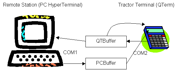
Messages can be sent in either direction. For example, when the user types in a message at the QTerm keypad, the information is sent to the PC. Messages move from right to left in the illustration above, read from the keypad over COM2, put in the QTBuffer, and written to the HyperTerminal over COM1. Alternatively, when the user types in a message at the HyperTerminal keyboard, the information is sent to the QTerm LCD. Messages move from left to right in the illustration above, read from the PC keyboard over COM1, put in the PCBuffer, and written to the QTerm LCD over COM2. Messages can be simultaneously typed in. Message data should not be lost.
You will need to extend the code developed in Section 2 of this lab to include two data buffers. Each data buffer is handled with its own read and write functions and respective serial ports. Data is added to QTBuffer from COM2, and removed onto COM1; vice versa for PCBuffer.
2. There are two steps to this part of the lab: Activity 1 and Activity 2.
Activity 1: Write assembly code to implement the QTBuffer and messaging from the QTerm to the HyperTerminal.
· Reuse the code to read the QTerm; write a new function to write to the HyperTerminal.
· Be sure to use the correct COM ports.
Activity 2: Write assembly code to implement the PCBuffer and messaging from the HyperTerminal to the QTerm.
· Reuse the code to write the QTerm; write a new function to read from the HyperTerminal.
· Be sure to use the correct COM ports.
The behavior of the software system can be partitioned as follows:
·
Reading QTerm for
input from its keypad (COM2)
·
Reading the PC for input from the keyboard (COM1)
·
Writing information to the QTerm (COM2)
·
Writing information to the PC (COM1)
Design Components
·
2 buffers - QTBuffer,
PCBuffer
·
Position variables for the buffers (i.e., where to put/get next data)
·
Read_QTerm - Reads up to 1 character from COM2 (QTerm) and places the
character into a buffer
·
Read_PC - Reads up to 1 character from COM1 and places the character
into a buffer
·
Write_PC - Writes up to 1 character to the PC via COM1
·
Write_QTerm - Writes up to 1 character to the QTerm LCD via COM2
Code Structure
Set up the code to read/write only one character at a time over a serial connection per pass through the main loop, repeatedly calling the functions to read and write characters.
MainLoop:
…
Call Read_QTerm
Call Read_PC
Call Write_QTerm
Call Write_PC
…
b MainLoop
All
functions should be non-blocking, meaning that they should not
loop inside of the function until a QTerm or HyperTerm character is pressed -
they should return in some fairly quick amount of time.
Compile, debug, and test the text messaging code. Demonstrate the program to the TA.
REMINDERS
The actual setup for the serial ports will still be done using the same methods as in previous labs. Be sure to call LCD_Init and PC_Init. These two functions initialize the serial ports to 9600 baud (bps) and clear out any outstanding communications that are pending.
Serial I/O Addresses
COM1 - Connected to PC
|
Name |
Address |
Description |
|
Com1Status |
0x0030500C |
COM1 Status (16 bits) |
|
Com1Data |
0x0030500E |
COM1 Data (16 bits) |
COM2 - Connected to QTerm
|
Name |
Address |
Description |
|
Com2Status |
0x00305024 |
COM2 Status (16 bits) |
|
Com2Data |
0x00305026 |
COM2 Data (16 bits) |